

Single Shaft Shredder Blades: Cutter Block Replacement Guide
Release time: 2026-10-26
Match single shaft shredder blades to the cutter geometry, mounting face, hole specification and installed cutting arrangement before choosing a material or comparing prices. Two square blocks can have the same nominal width and still differ in seating, thread, edge position or cutting profile. Those differences can prevent a replacement from working in the existing holder.
For a replacement inquiry, identify the machine and cutter position, retain an unworn reference if available, and describe why the current block was removed. A photograph of its top face is a useful start, but the underside and mounting details often decide whether the proposed part fits.
Send NJDETE the drawing, sample identification and both-face photographs for a cutter-block specification review. State whether the inquiry covers blocks alone or the associated holders, fasteners and counter-knives.
Identify the Cutter Block and Its Assembly
In a typical screened single-shaft machine, replaceable rotor cutters work against fixed counter-knives. The rotor, feed system and screen form a cutting arrangement. Replacing one component needs to preserve its relationship with the others.
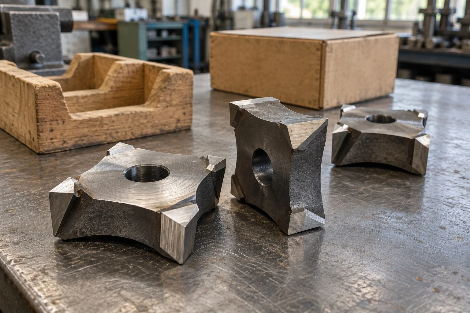
Square, concave and crown-style blocks are common descriptions, but they do not define one interchangeable part. Some rotors use other knife forms. Establish the actual design instead of assuming that every single-shaft shredder uses the same block.
| Part being identified | Information needed for replacement | A frequent purchasing omission |
|---|---|---|
| Rotor cutter block | Drawing or part identity, profile, seating face, hole and edge position | Only the top-view width is supplied |
| Cutter holder or support | Holder identity, contact geometry, condition and any locating feature | A worn support is treated as suitable because the new block can be attached |
| Fixed counter-knife | Its own dimensions, position and approved relationship with the rotor cutter | A counter-knife is mistaken for another rotor block |
Do not use a double-shaft disc cutter drawing to specify a square rotor block. Disc bore, hook count and stack thickness answer a different assembly question. The shredder blade design guide focuses on that disc-type arrangement; this guide covers replaceable blocks and their mounting interfaces.
For machine selection rather than parts replacement, use the Сравнение одновальных и двухвальных моделей. A cutter inquiry does not establish that an entirely different machine configuration suits the material.
NJDETE Catalogue References to Confirm
NJDETE’s catalogue includes a single-shaft blade family described with a square form, curved sides, a central tapped hole and four cutting tips. Cr12MoV is the material listed for that family. The catalogue also shows two size notations.
| Catalogue item | Listed reference | Confirmation needed for an order |
|---|---|---|
| Single-shaft blade material | Cr12MoV | Finished-part material specification, treatment and inspection requirements |
| Cutter form | Square form, curved sides, central tapped hole and four tips | Exact profile, hole specification, seating and machine compatibility |
| Size notation | 40 × 40 × 25 | Units, dimension order, datums and drawing tolerances |
| Size notation | 60 × 60 × 30 | Units, dimension order, datums and drawing tolerances |
The source does not explicitly state the units for these two notations. They are catalogue identification references here, not approved millimetre dimensions. It also does not provide a universal thread, edge radius, finished hardness or compatible-machine list. Confirm those details on the quotation and approved drawing.
This distinction prevents an early reference from becoming an unintended manufacturing instruction. If your purchasing list says “40 mm blade,” retain that description as the customer’s starting requirement, then resolve the complete part geometry before release.
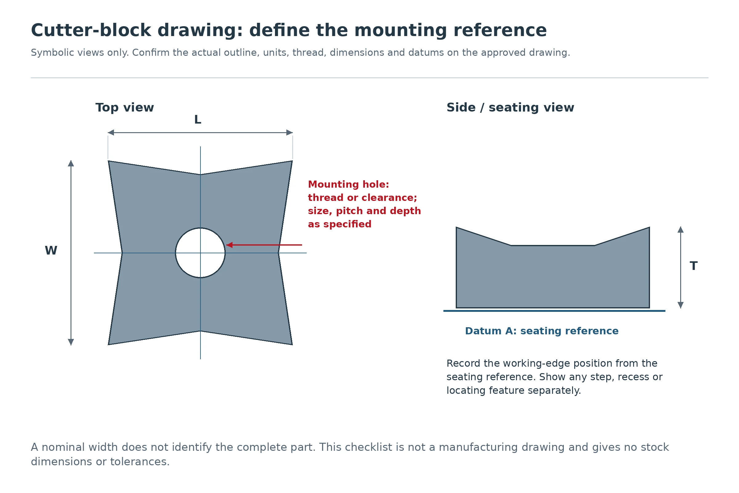
Measure the Mounting Features That Decide Fit
Use the approved drawing when one exists. If a sample must be measured, distinguish original features from wear, earlier grinding and damage. A badly worn corner can help explain failure but may not provide the intended new-part profile.
For a preliminary review, provide top, bottom and side photographs with the sample identified. Keep the same reference faces throughout the measurement record. A sketch without datums can make two correct measurements describe different surfaces.
| Feature | What the specification should resolve | Why it affects the purchase |
|---|---|---|
| Length, width and body thickness | Dimension direction, units and reference surfaces | Nominal size can omit the seating or working-edge position |
| Seating face | Flat or profiled contact, step, recess and locating feature | The holder must support and locate the intended surfaces |
| Mounting hole | Threaded or clearance hole; size, pitch, depth and any counterbore or chamfer | A visually similar hole may require a different fastening arrangement |
| Cutting profile | Concavity, corner form, bevel and edge position from the seating datum | Changes can alter engagement and the relationship with the counter-knife |
| Orientation and position | Drawing reference, cutter family and rotor position | A mixed rotor may use more than one part or orientation |
| Finished condition | Required inspection characteristics and reporting method | Outside size alone does not establish an acceptable finished cutter |
Confirm a thread with the specified inspection method. A bolt that appears to enter the hole does not verify the complete thread or its usable engagement. Fastener grade, length, reuse policy and tightening requirements belong to the approved assembly documentation, not a generic cutter-size table.
Also distinguish knife material from any coating or surface treatment. A surface colour is not evidence of the underlying grade, heat treatment or remaining service life.
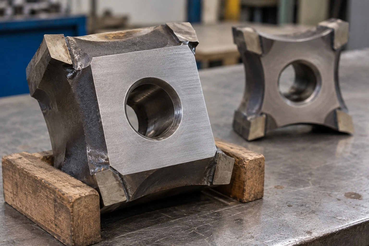
Decide Whether to Index, Replace or Assess the Holder
Indexing means presenting another permitted cutting edge or corner on a cutter designed for that use. It is a maintenance decision governed by the particular cutter and assembly. Four visible corners do not establish four usable service periods.
Record the reason for removal before deciding what to buy. Preserve the part identification and rotor position with the observation so a repeated problem can be traced.
| Recorded condition | Decision to investigate | Evidence needed before release |
|---|---|---|
| Used edge has reached its limit; another permitted edge is intact | Possible indexing under the approved procedure | Reusable body, mounting feature, seating and the manufacturer’s acceptance conditions |
| Chip or crack affects the cutter body or mounting region | Replacement or specialist assessment | Extent of damage and the associated support condition |
| Damage returns at the same rotor location | Holder, contact or assembly investigation | Position history, contact evidence and comparison with an unaffected location |
| Several blocks wear differently | Review feed, position, counter-knives and setup | Comparable observations across the rotor and actual operating conditions |
| A block no longer locates or seats as intended | Hold the assembly for assessment | Cutter and holder geometry; attaching the part is insufficient evidence of correct support |
Any access, inspection, indexing or replacement follows the machine’s isolation and maintenance procedure, carried out by authorised personnel. This article defines the information needed for a parts decision; it does not provide a machine-specific replacement sequence.
Regrinding also needs a design review. Removing material may change the working profile, edge position or adjustment range. Obtain the permitted returned geometry before ordering a sharpening job. A practice suitable for a straight granulator knife is not automatically suitable for an indexable block.
Match the Steel to the Actual Duty
Start with the established part specification and the observed wear mechanism. Identify the incoming material, reinforcement or fillers, expected contamination, largest sections and abnormal events. “Plastic” or “wood” alone leaves too much of the cutting duty undefined.
If the existing part fails through progressive wear, a material review may be useful. If it breaks after impact or shows repeated local contact, changing the steel without resolving the cause can leave the buying problem unchanged. Keep the holder and working profile in the review.
Cr12MoV is the NJDETE catalogue reference for this family. It is not evidence that every block should use that grade, or that another supplier’s steel designation is interchangeable. Specify the agreed material and finished condition for the actual order. The shredder blade materials guide explains the wider wear-and-impact decision without replacing the part drawing.
Do not transfer a hardness range from a different knife family to this block. If hardness is an acceptance characteristic, the order should identify the range, test method, test location and record required. The same principle applies to dimensional and profile inspection.
Compare the Replacement Quote on One Scope
Make the supplied quantity and part scope explicit. A price for one loose cutter cannot be compared directly with a position-labelled set containing fasteners and counter-knives.
| Quotation line | Resolve before comparing prices |
|---|---|
| Cutter identity | Part or drawing reference, revision and permitted alternative |
| Material and finished condition | Agreed grade, treatment and acceptance characteristics |
| Mounting and profile | Seating, hole, working-edge geometry and inspection scope |
| Quantity and grouping | Number of each part, positions served, spare quantity and set labelling |
| Associated components | Holders, bolts, washers and counter-knives included or excluded |
| Records and commercial scope | Inspection documents, packaging, delivery basis and destination |
If the proposed material or geometry differs from the established part, identify the change in writing. Agree how compatibility and the resulting cut will be evaluated. A supplier’s use of “replacement” does not establish an approved substitution.
Packaging should preserve edge condition and part identity through transport. Ask for individual separation where appropriate, clear part and batch identification, and the agreed accompanying documents. These details are especially useful when several visually similar blocks are ordered together.
Plan Acceptance and Stock by Cutter Position
Keep receiving inspection separate from acceptance in the installed assembly. Receiving checks confirm the supplied part and records against the order. Assembly and production checks confirm the approved relationship and outcome on the machine. Neither should be replaced by an informal “looks the same” decision.
Use a simple position record containing the rotor location, cutter identity, active edge or index where applicable, observed condition, removal date and reason. If the design uses several cutter types, keep them separate in the stock list. Do not infer total order quantity by multiplying an assumed edge count by the number of visible holders.
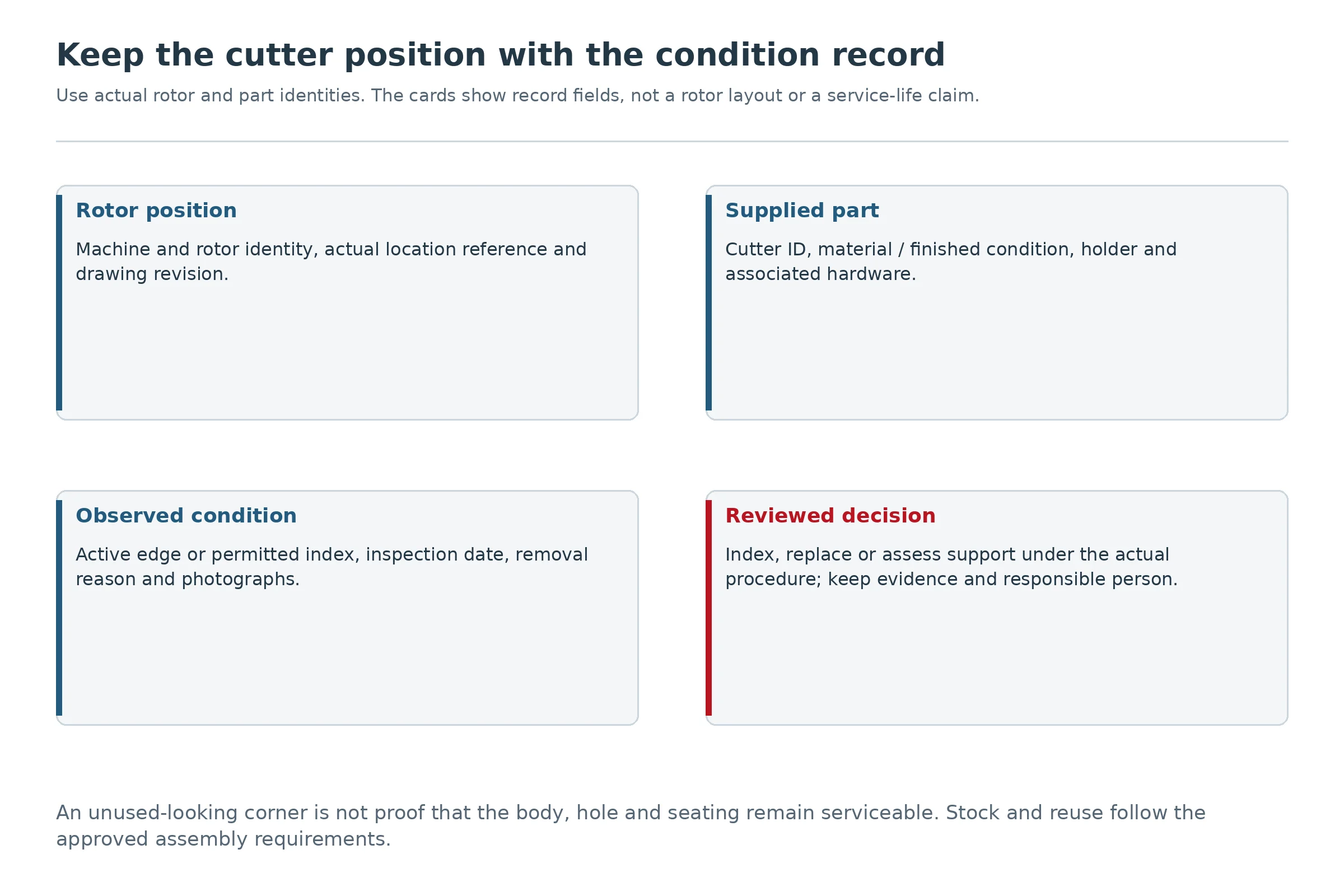
Set stock against the actual installed quantities, observed consumption, supplier replenishment time and the cost of an interrupted production task. Include the associated components that the maintenance procedure requires, rather than stocking only the cutting blocks.
For the broader replacement planning process, see the Руководство по замене ножей измельчителя. Use this block-specific record alongside it so the mounting and position details remain visible.
Часто задаваемые вопросы
Are single shaft shredder blades interchangeable between machines?
Not on the basis of the category name. Confirm the cutter profile, body, seating, hole, working-edge position and actual machine assembly. A similar square outline does not establish compatibility.
Is a 40 mm or 60 mm cutter description enough for a quote?
It can identify a starting size family, but the quotation still needs the complete drawing or sample review. Resolve units and dimension order, thickness, profile, mounting and finished-part requirements.
Can every square cutter use four cutting corners?
No. The permitted index positions and reuse limits depend on the design and condition. A damaged body, mounting hole or seating feature can make an apparently unused corner unsuitable for further service.
Should the counter-knives be replaced with the rotor blocks?
Assess the actual counter-knives, holders and approved cutting relationship. They are separate parts with their own condition limits. A new rotor block alone does not establish that the complete arrangement is acceptable.
Can a different steel grade solve repeated chipping?
Only a review of the cause can establish whether a material change helps. Record impact, contamination, support, unintended contact and the affected position. Do not treat another grade name as a substitute for that investigation.
What if there is no drawing or readable part number?
Provide the machine identity, cutter position, top and underside photographs, side views, preliminary measurements and service history. Retain an unworn reference if available. Treat the resulting dimensions as preliminary until the replacement specification is approved.
Send NJDETE a Cutter-Block RFQ
Send the machine make and model, existing part or drawing reference, rotor position, sample condition, both-face and side photographs, dimensions with units, mounting details, material being processed and the reason for replacement. State the required quantities and whether the scope includes associated hardware or counter-knives.
You can review the NJDETE shredder-parts range и published blade families before submitting the inquiry. Catalogue references support identification; the approved specification determines the supplied part.
Ask NJDETE to review your single-shaft cutter-block replacement. Specify whether the task is a like-for-like part, a documented alternative or a larger holder-and-knife review so the quote covers the work you need.