

Как измерить размеры ножей измельчителя для замены
Release time: 2026-09-30
If you are ordering replacement cutters, an outside dimension and a machine model are a starting point—not a complete specification. Two blades can look alike and still differ in bore fit, thickness, tooth orientation or the spacer arrangement that determines how the assembly goes together.
To measure shredder blades for replacement, record the cutter profile, face-to-face thickness, bore geometry and locating features, then document the spacers and assembly sequence. Use an approved drawing to establish tolerances. Treat measurements from worn parts as evidence of their current condition, not automatically as the dimensions for new parts.
Your first purchasing decision is therefore straightforward: do you have an approved drawing, an unworn spare, or only used components? That determines what the supplier can quote confidently and what needs checking before production.
Start With the Best Reference You Have
| Available reference | What it helps you establish | What still needs agreement |
|---|---|---|
| Approved drawing with revision | Nominal geometry, datum references and specified tolerances | Whether it matches the current machine configuration |
| Unused spare with traceable part number | A physical reference for shape and dimensions | Drawing approval and material requirements |
| Used cutter and matching spacer | Existing arrangement, wear locations and approximate dimensions | Original size, intended fit and whether the set has been modified |
| Photos and a machine model only | Initial product identification | Dimensions, interface details and manufacturing approval |
An approved drawing is normally the strongest basis for a repeat order. A used sample is valuable when a drawing is missing, but it creates a reverse-engineering task. Tell the supplier which situation applies before comparing prices.
If you are still deciding whether the existing cutters should be replaced, use the Руководство по замене ножей измельчителя first. This article focuses on the information needed once you are preparing a replacement enquiry.
How to Measure Shredder Blades: The Dimensions That Matter
Work with safely removed, cleaned components on a stable surface. Removal and access to the machine belong in the equipment manufacturer’s isolation and servicing procedure; do not reach into a cutter chamber to obtain these measurements.
Before recording values, note the units, instrument used and condition of the measured surface. Keep photographs, measurements and component labels connected. A precise number is of little use if nobody can identify which cutter or surface it describes.
| Feature | What to record | What it means for your purchase |
|---|---|---|
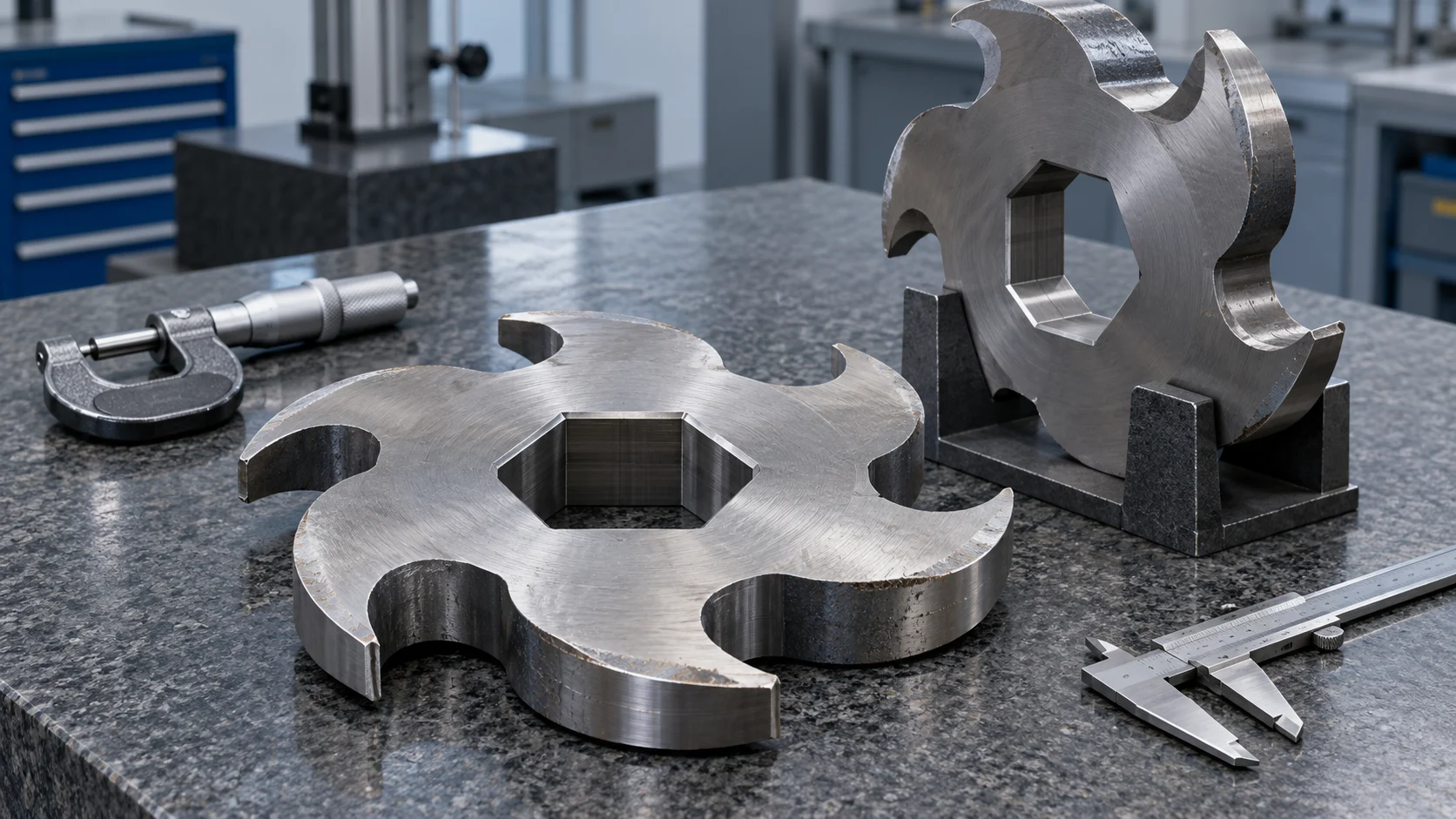
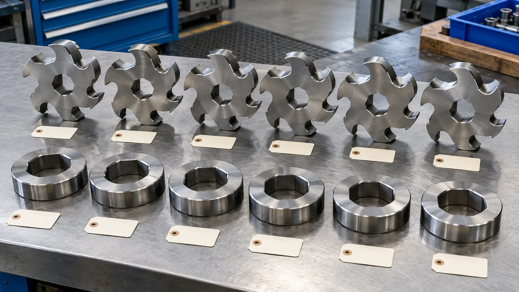
| Outside profile | Tooth count, outline and the drawing’s defined outside envelope | Identifies the cutting geometry; one maximum span does not define every tooth |
| Blade thickness | Face-to-face readings at identified sound locations | Affects the assembled stack and compatibility with adjacent components |
| Bore | Shape and dimensions referenced to specified faces or features | Determines the interface with the shaft |
| Keyway, spline or locating feature | Geometry, position and its reference datum | Controls location and torque-transfer compatibility |
| Tooth direction and indexing | Front/back views and orientation relative to the bore | Helps prevent ordering a mirrored or incorrectly indexed part |
| Spacer | Bore, outside profile and thickness | Establishes how the replacement cutter fits the existing arrangement |
| Recess, shoulder or counterbore | Side, diameter/profile and depth where present | Prevents an apparently similar part from seating incorrectly |
1. Define the outside profile, not just “diameter”
On a toothed cutter, a caliper reading between whichever two points are easiest to reach may not represent the outside diameter defined on the original drawing. This matters when the tooth pattern does not provide opposing tips.
Send a straight-on photograph of the complete face, identify the tooth count and supply the drawing or profile file when available. If you submit a tip-to-tip measurement, mark the two points used. Avoid describing that span as the nominal cutting diameter unless the geometry supports that interpretation.
For a supplier, this separates a useful measured span from an assumed design dimension. For you, it reduces the risk of receiving a cutter with the right quoted “diameter” but the wrong working profile.
2. Measure thickness away from damaged edges
Record thickness at several identified locations on sound faces. Note burrs, corrosion, impact damage and any previous face grinding. Do not average unlike readings into one clean-looking number without recording the variation.
Use a suitable instrument for the feature and tolerance being assessed. Mitutoyo’s caliper measurement guidance explains that measuring force affects repeatability. An extra decimal place on a display does not establish that the complete measurement is accurate to that decimal place.
Your enquiry should separate three things: the measured thickness, the intended new-part thickness and the permissible tolerance. The supplier needs the second and third to manufacture; the first helps explain the sample.
3. Describe the bore unambiguously
For a hexagonal bore, distinguish across flats from across corners. They are different dimensions. Include a face photograph and mark the opposing surfaces referenced by your measurement. Record internal corner details or reliefs when they are part of the fit.
For keyed round bores, identify the bore and keyway separately. For splines or more complex profiles, supply the specification or request an agreed inspection method. A photograph of a caliper in one position cannot fully define these interfaces.
Do not invent a clearance allowance by subtracting a convenient amount from a worn bore measurement. The target fit must be established from the mating shaft, design information and an approved replacement drawing.
4. Preserve tooth orientation and assembly position
Label the two faces of the sample consistently, then photograph both. Where the cutter’s tooth pattern is indexed relative to the bore, make that relationship visible. If the machine uses different cutters in different positions, identify each part separately.
A photograph taken from the opposite face can make the same component look reversed. Clear labels are cheaper than resolving a disagreement after a replacement set arrives.
Measure the Spacer Arrangement as Part of the Order
A replacement cutter belongs to an assembly. Record the spacer types, their thicknesses and where they sit. If your enquiry covers a complete set, include the sequence from one defined end of the shaft and identify any end spacers or other locating components.
A simple example of thickness accumulation
Consider a hypothetical stack containing 20 cutters. If every replacement cutter is 0.03 mm thicker than the intended value, the cutters alone add:
20 × 0.03 mm = 0.60 mm
That is a planning example, not a NJDETE tolerance specification or an acceptable clearance. Spacer deviations and other locating dimensions must also be considered. Errors do not necessarily all have the same sign; the example shows why a consistent thickness offset can matter across a set.
For your order, ask for the permitted individual dimensions and the relevant assembled dimensions. Whether the resulting stack is acceptable depends on the machine design, not on whether each blade looks close to the sample.
What You Cannot Establish From Dimensions Alone
Matching dimensions do not prove matching cutting performance. Geometry is one part of the specification; material condition and the application remain separate decisions.
A worn cutter’s appearance does not reliably identify its steel grade, heat treatment or original hardness. If those requirements matter to the order, provide existing records or agree what evidence is needed. Do not choose a higher hardness simply because it sounds more durable: the cutting application and failure pattern also matter.
Likewise, a chipped edge does not by itself establish why a blade failed. Describe what the machine processes, the foreign material encountered, the location of damage and whether the issue repeats across the set. Photographs of damage help frame the discussion, but they do not replace a diagnosis.
Ознакомьтесь с NJDETE double-shaft shredder blades product page alongside your dimensional information. Keep the enquiry focused on the actual machine, cutter arrangement and material being processed.
Prepare an RFQ the Supplier Can Actually Use
Send one coherent reference package rather than dimensions scattered across several messages. Put a component identifier on every photograph and measurement sheet.
| Include in your enquiry | Detail that prevents avoidable clarification |
|---|---|
| Machine identification | Manufacturer, model and relevant configuration changes |
| Drawing or sample reference | Part number, revision and whether the sample is used or unused |
| Dimension sheet | Units, measurement locations and unknowns clearly marked |
| Cutter and spacer quantities | Quantity for each distinct part, not only a total weight |
| Application description | Feed material, attachments, contamination and recurring failure pattern |
| Required delivery scope | Individual cutters, a matched set, spacers or additional components |
| Acceptance requirements | Which drawing, dimensions and material documents will govern approval |
Before authorizing production, ask the supplier to confirm the drawing revision, quantities, material specification and inspection scope in writing. Separate confirmed requirements from items still awaiting sample review. A quotation can be useful for budgeting before every detail is resolved; production approval needs a sufficiently defined specification.
Questions Buyers Ask Before Sending a Sample
Can you quote from photos without a drawing?
Photos can support an initial assessment, especially when they show both faces, the edge and the mating arrangement. Ask whether the price is preliminary or based on a confirmed specification. Manufacturing from an approved drawing may require additional measurement or sample review before the order is released.
Should I send the most worn blade or the least worn one?
If possible, provide a sound reference for geometry and a separately identified worn component to explain the problem. An unused spare or approved drawing is more useful for establishing intended dimensions than a heavily damaged cutting edge. Ask the supplier which physical samples are needed before shipping.
Should I order one cutter or replace the complete set?
Base that decision on the condition and dimensional compatibility of the remaining assembly. One replacement may be appropriate where the rest of the set is serviceable and the replacement can be matched to it. If several parts are worn, reground or untraceable, request an assessment of the set and spacers before choosing the order quantity.
Can a drawing made from an old blade be reused for future orders?
Yes, once the dimensions, interfaces and requirements have been reviewed and the drawing is approved for the intended machine. Give it a controlled revision and retain the approval record. Future changes to the shaft, spacer arrangement or cutter profile should trigger a review rather than silent reuse of the old file.
Send the Information That Determines Fit
For your next replacement order, start with the best reference available, identify each cutter and spacer, and distinguish current wear measurements from intended new-part dimensions. That gives the supplier a clear basis for confirming fit and preparing a comparable quotation.
Send NJDETE your blade drawing and replacement enquiry with photographs, machine identification, quantities and application details. Mark anything you cannot confirm so it can be resolved before manufacturing approval.