

تصميم شفرات آلة التقطيع: شكل الأسنان، والسماكة، وملاءمة قطع الغيار
تاريخ الإصدار: 16 أكتوبر 2026
A useful shredder blade design matches the incoming material, required output and complete cutting assembly. Tooth count, body thickness and material grade are separate parts of that decision. For replacement purchasing, establish the approved original specification before comparing a different profile or ordering from a worn sample.
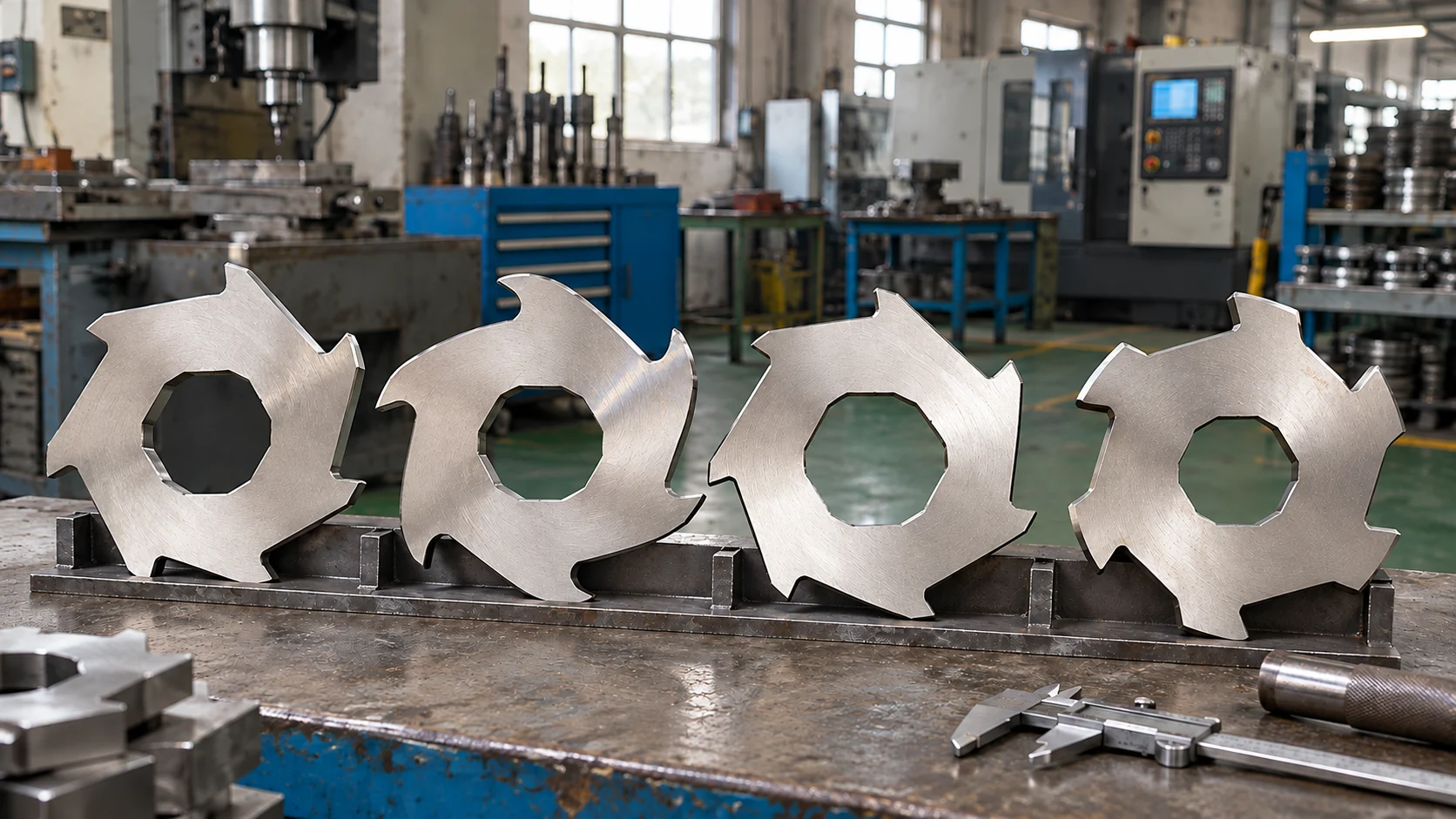
Illustrations are AI-generated concept visuals. They are not manufacturing drawings, measured-part records or photographs of a verified NJDETE installation.
This guide focuses on disc-type cutters in double-shaft shredders. Single-shaft cutting blocks, straight granulator knives and other blade systems have different mounting and cutting arrangements. Use the relevant machine’s technical documentation rather than transferring dimensions or settings between categories.
For a buyer, the practical question is usually whether a proposed cutter will fit, engage the actual material and deliver an acceptable result. The following framework combines tooth-profile, thickness and spacer questions into one specification review.
Start With the Material and Required Output
Describe the material as it enters the machine. Include its form, dimensions, stiffness, normal contamination and how it is presented. A material name alone leaves important differences unresolved: thin film, a rigid container and a dense plastic offcut create different feeding tasks even when they belong to the same polymer family.
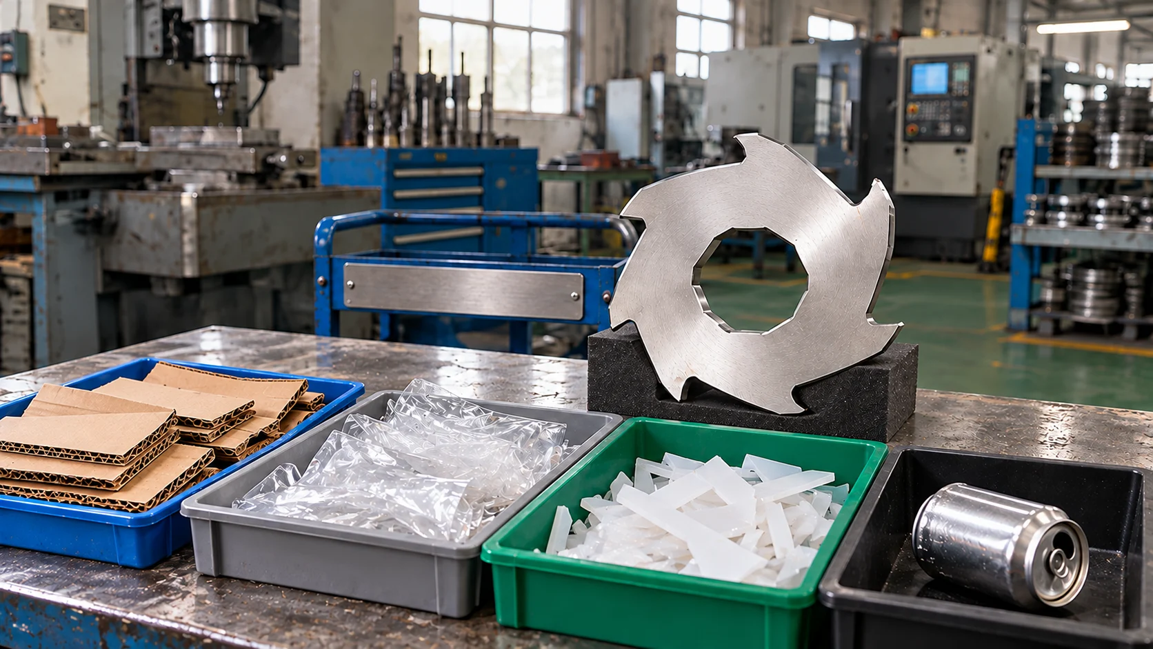
Also define the receiving process. Transport volume reduction and preparation for another cutting stage do not necessarily require the same output. Record which long pieces, connected strips, fines or oversized fragments would be rejected. A small-looking handful does not establish that the complete discharge meets that requirement.
| Feed example for review | Describe before comparing designs | Evidence to request |
|---|---|---|
| Rigid HDPE or PP items | Item size, wall thickness, nesting and contamination | Representative feeding and output record |
| Film or flexible sheet | Loose or bundled form, length and permitted preparation | Observed presentation and any wrapping or bridging |
| Cardboard | Folded condition, coatings, tape and fasteners | Accepted feed and the receiving route |
| Defined metal containers | Material, wall form and excluded contents | Written application scope and relevant trial |
| Mixed or uncertain loads | Routine composition and objects requiring removal | Sorting responsibilities and accepted-feed limits |
These are review questions, not a claim that one NJDETE cutter can process every listed stream. The دليل مواد آلات التقطيع الصناعية gives broader context; the blade order needs the scope specific to your machine and material.
Define the Complete Cutter Geometry
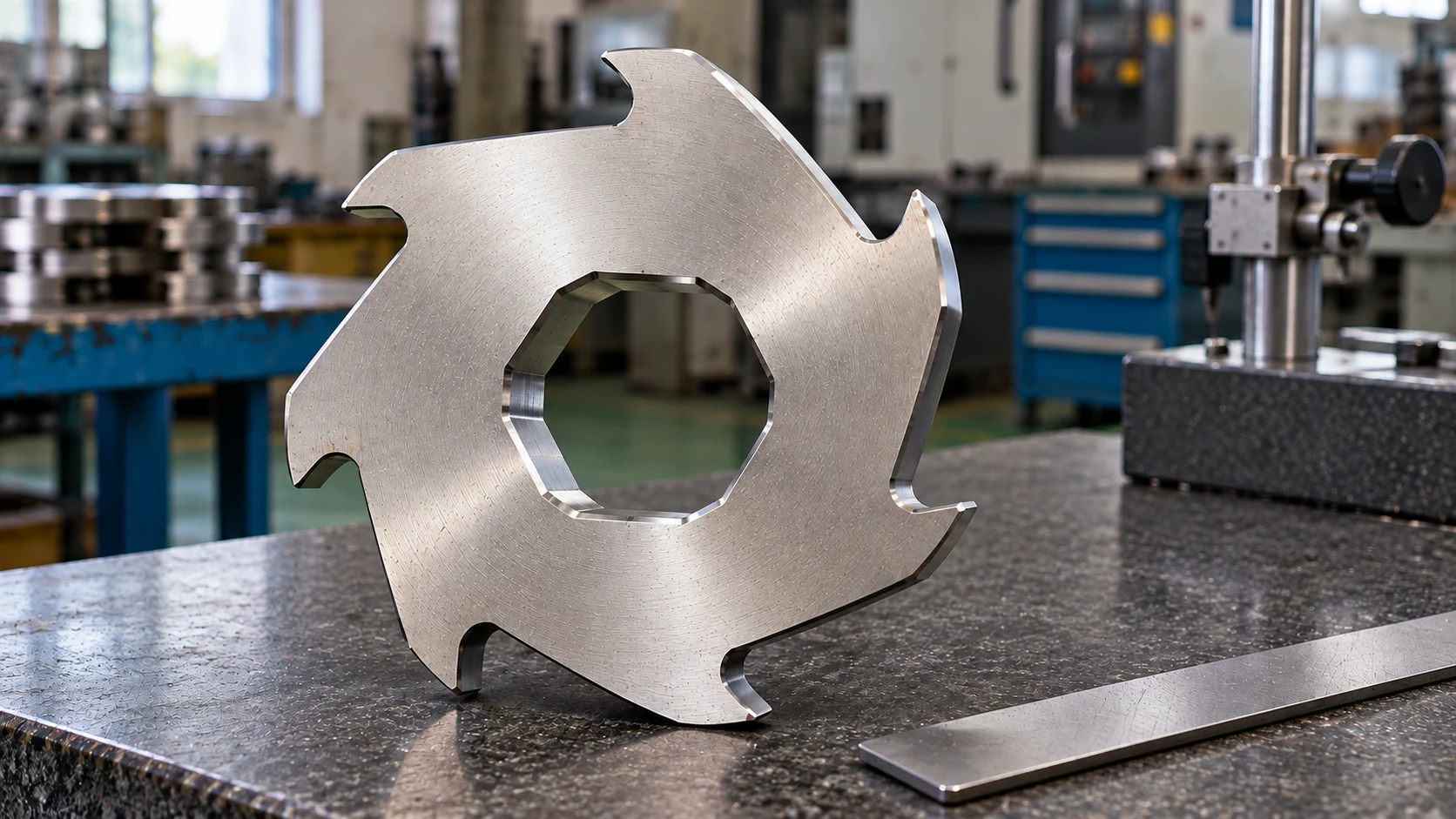
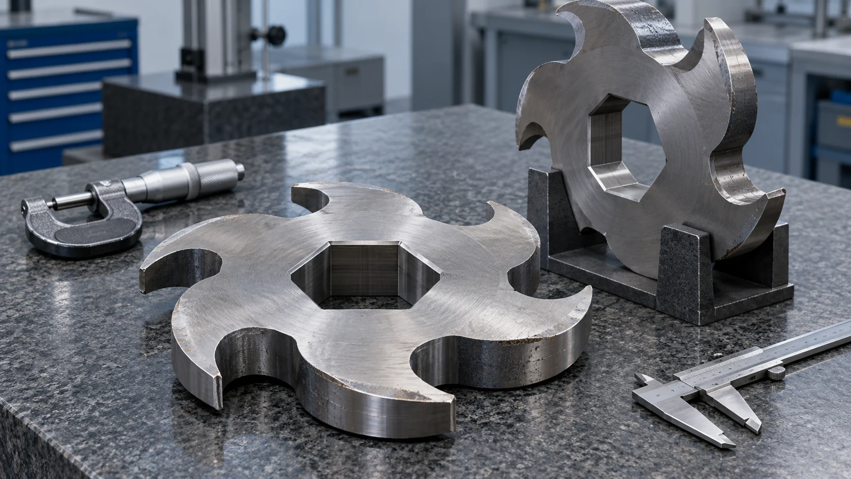
Two discs can share a diameter and tooth count while differing in their bore, hook outline, edge form or assembly orientation. Specify the part by a controlled drawing and revision where available. A catalogue picture is useful for identification but leaves dimensions and tolerances unresolved.
Start with machine identity, cutter part number and the applicable assembly reference. Record whether the same part appears at every position or whether the two shafts use different types. Agree which face and shaft end define the viewing reference so that clockwise, left and right have an unambiguous meaning.
| Design feature | Purchasing confirmation | Insufficient substitute |
|---|---|---|
| Outside diameter | Approved nominal dimension and tolerance | Approximate diameter from a photograph |
| Bore and drive interface | Complete shape, dimensions and reference orientation | A statement that both bores look hexagonal |
| Body thickness | Defined measurement faces and applicable tolerance | One measurement on a damaged edge |
| Tooth profile and count | Complete outline, working features and revision | Tooth count alone |
| Handing or orientation | Defined viewing direction and assembly position | Unreferenced left/right descriptions |
| Associated components | Spacer types, neighboring parts and assembly requirements | Confirmation that the disc slides onto the shaft |
The manufacturer of the Shred-Tech ST-50 describes its knife profile and configuration as application-related and identifies shaft, knife and spacer dimensions within the machine design. This supports reviewing the components together; its dimensions and operating claims do not specify an NJDETE replacement.
Choose Tooth Profiles by Engagement, Not Appearance
Hooked features can help draw material into the cutting zone, while opposing working edges contribute to cutting. The useful result depends on the whole arrangement and feed presentation. A visually aggressive hook or a larger number of teeth does not establish better performance on every stream.
If material is not engaging consistently, retain observations of its shape, loading method and behavior at the chamber. Distinguish material that bridges or is poorly presented from a change caused by cutter wear or damage. Otherwise, a new profile may be proposed for a problem outside the cutter geometry.
Ask the supplier why an alternative profile suits the described duty, which assembly features remain compatible and what trial would verify the proposal. An explanation should connect the design to the actual problem rather than only comparing tooth counts.
Separate Original Geometry From Service Damage
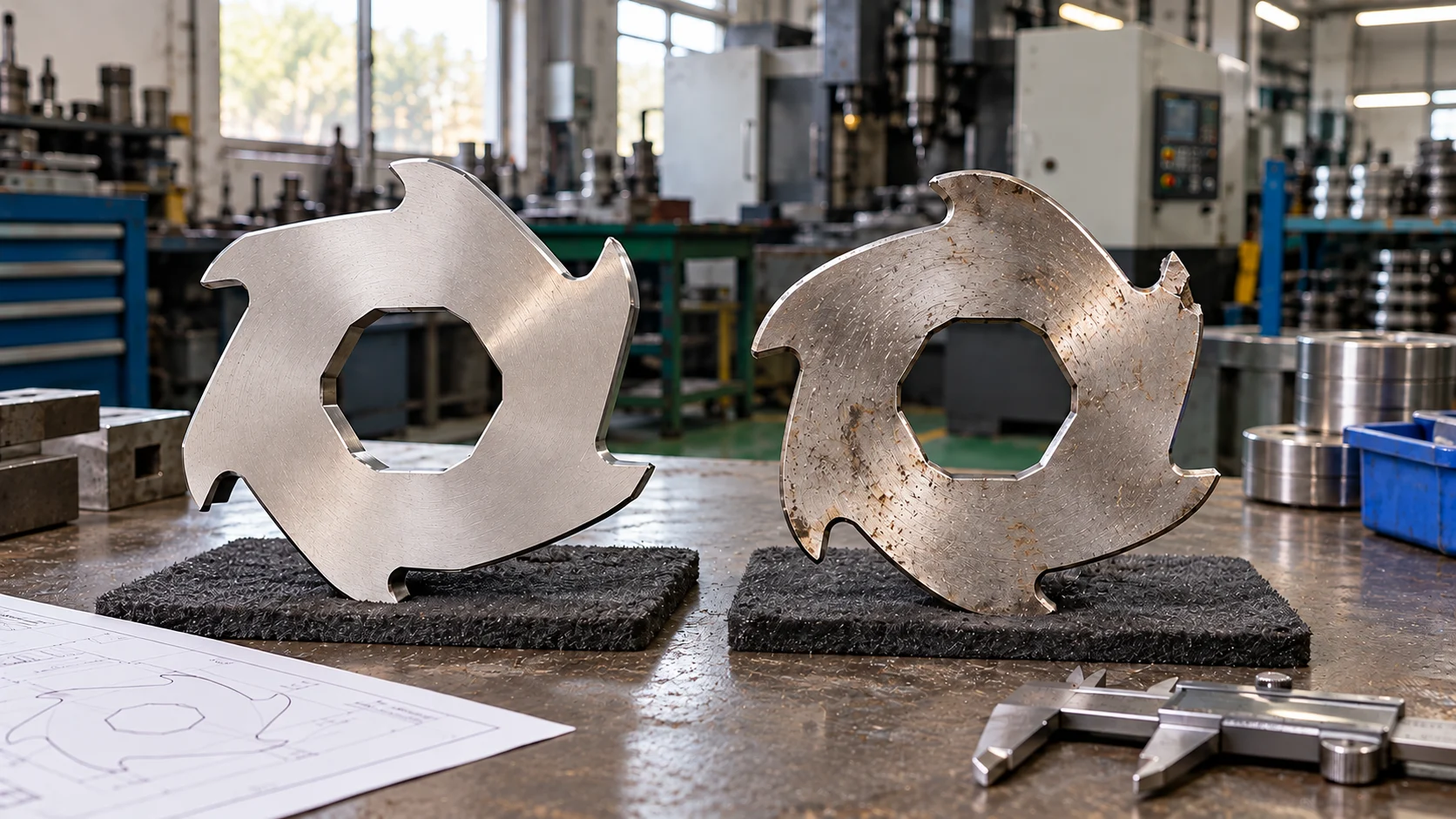
Shred-Tech’s knife-wear guidance identifies missing or damaged hooks and rounded working edges as inspection considerations. These observations help frame a review; they do not provide a universal remaining-life calculation for another machine.
Keep chipped areas, missing hooks and earlier regrinding identifiable in a used sample. The worn outline may no longer represent the original part. Where possible, compare it with an approved drawing, a traceable unused spare or the original service record.
Avoid treating a photograph of one failed disc as a complete diagnosis of the machine. Keep its shaft position, nearby component condition and known incident history with the sample. That evidence helps the technical team decide whether the proposed order is an equivalent replacement or a design change.
Relate Blade Thickness to the Cutting System
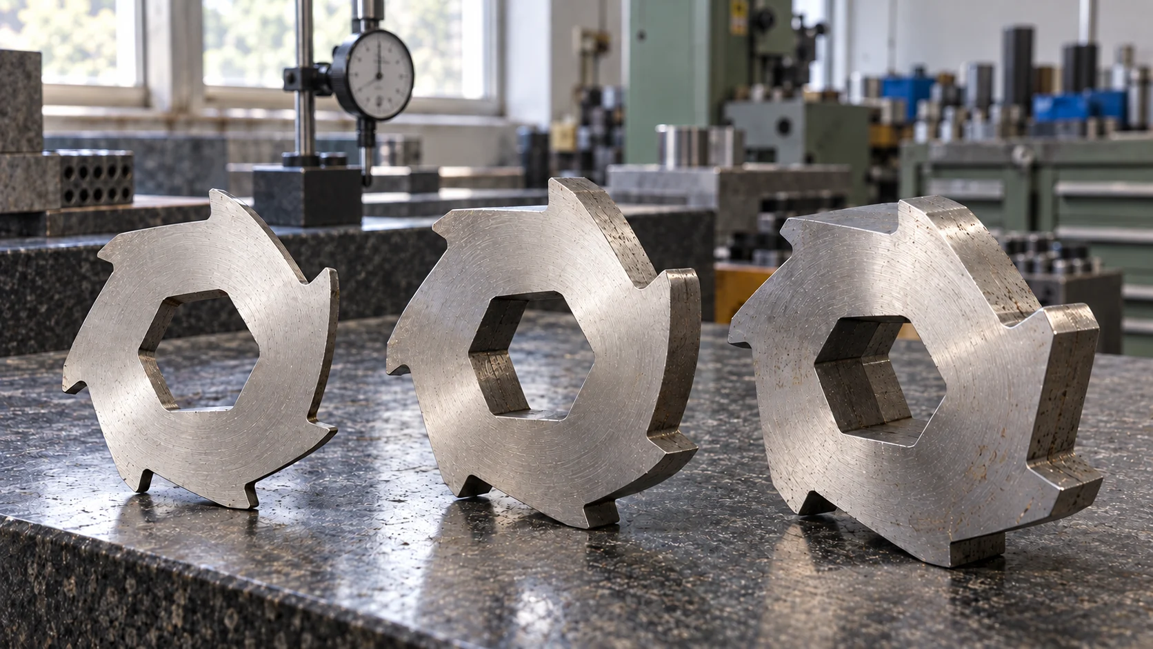
Shredder blade thickness is a component dimension. It can influence the cutting arrangement, but it does not guarantee that every piece of discharged material will have that dimension. A required output size and a replacement thickness therefore need separate specifications.
For example, a 10 mm cutter should not be described as a guarantee of exclusively 10 mm output. This is a hypothetical dimensional example, not an NJDETE specification. Actual output must be assessed against the agreed receiving requirement using representative material and the proposed configuration.
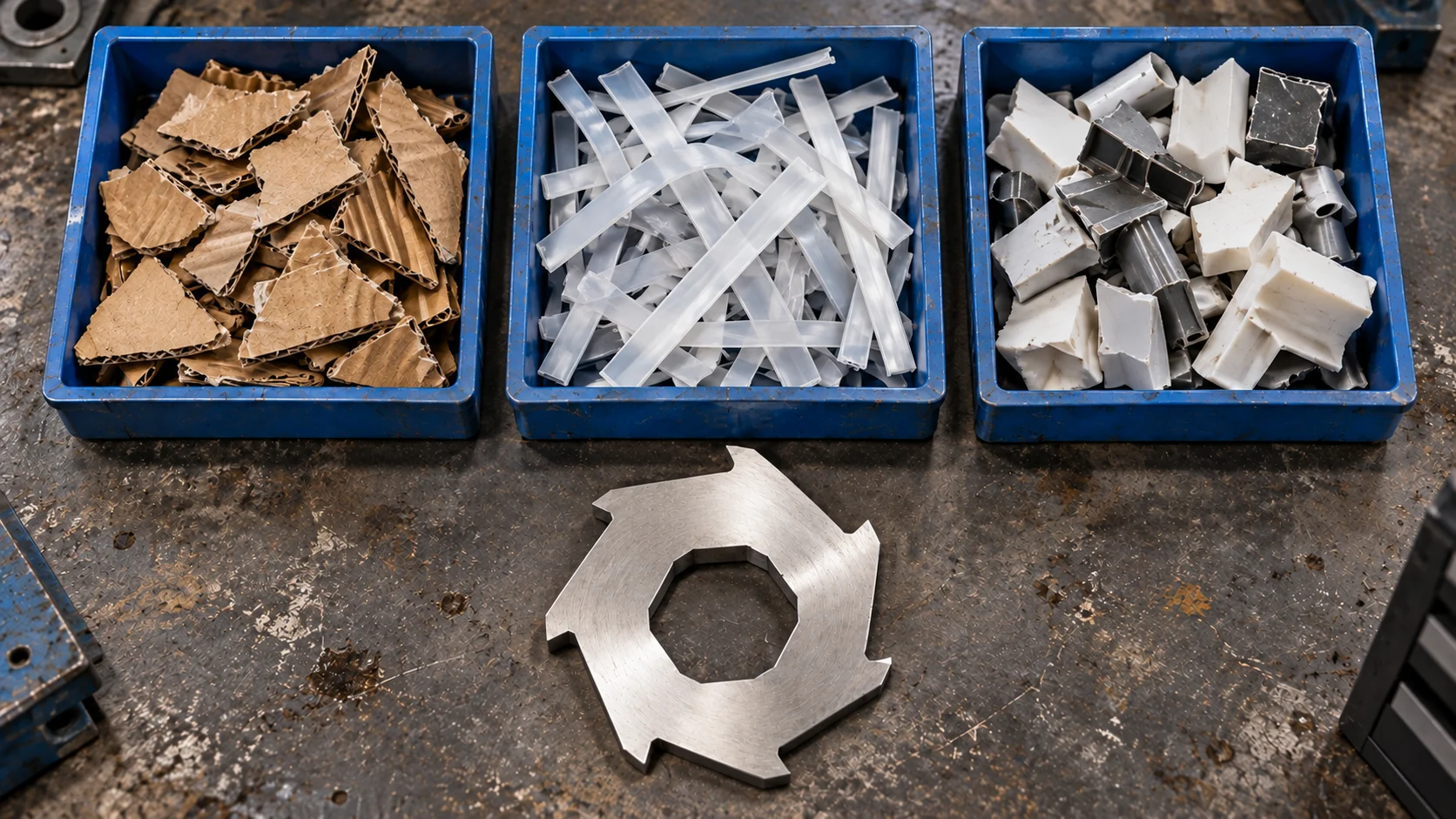
If the objective is to reduce oversized or connected pieces, describe the rejected fraction and provide an output sample. Ask which part of the process needs review, including feeding, cutter arrangement and any subsequent size-reduction stage. A thinner disc alone is not an acceptance test.
Treat any proposed thickness change as a revision. Ask which spacers, positions, neighboring components and overall assembly requirements are affected. Keep the party responsible for approving the machine arrangement identified separately from the party manufacturing the individual discs.
Include Spacers and Cutter-Stack Positions
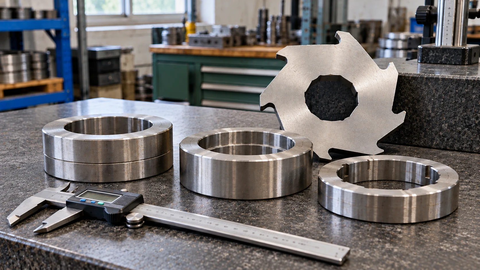
Spacer rings are part of the assembly specification. Identify their individual types, dimensions, quantities and positions where they fall within the purchase scope. Do not assume every ring has the same width or that a new cutter order automatically includes matching spacers.
Used rings also carry a service history. Scuffed faces, burrs, damage or previous modification need to remain associated with the part when determining a replacement baseline. Decisions about reuse should follow the applicable equipment criteria and responsible technical review.
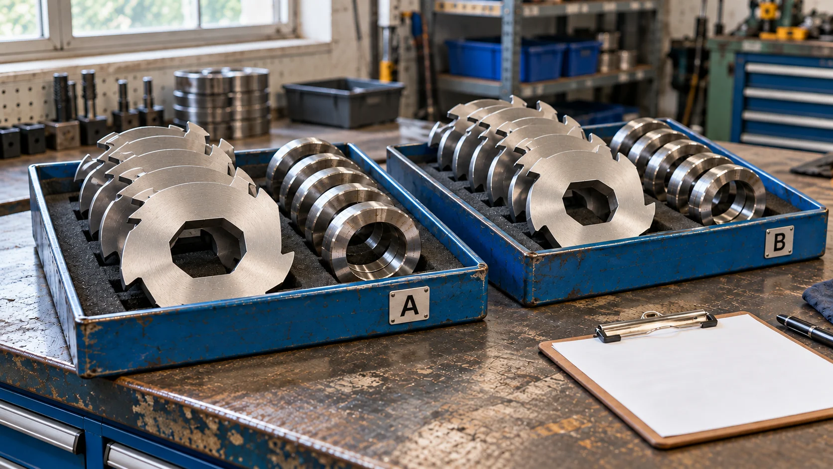
Keep both shafts distinguishable in the position record. Identify any special end components or differing cutter and spacer types. This record supports the approved service procedure; it is not a universal disassembly sequence.
A plausible total stack length does not establish that each individual component is correct. Different combinations may occupy similar space while leaving local relationships unresolved. Record both the individual part specification and the approved complete arrangement before authorizing substitutions.
Clarify what the supplier means by a set. It may mean cutters only, cutters with specified spacers or an assembled unit. Define quantities by part type and drawing revision so that purchasing and maintenance are discussing the same delivery.
Measure a Traceable Baseline
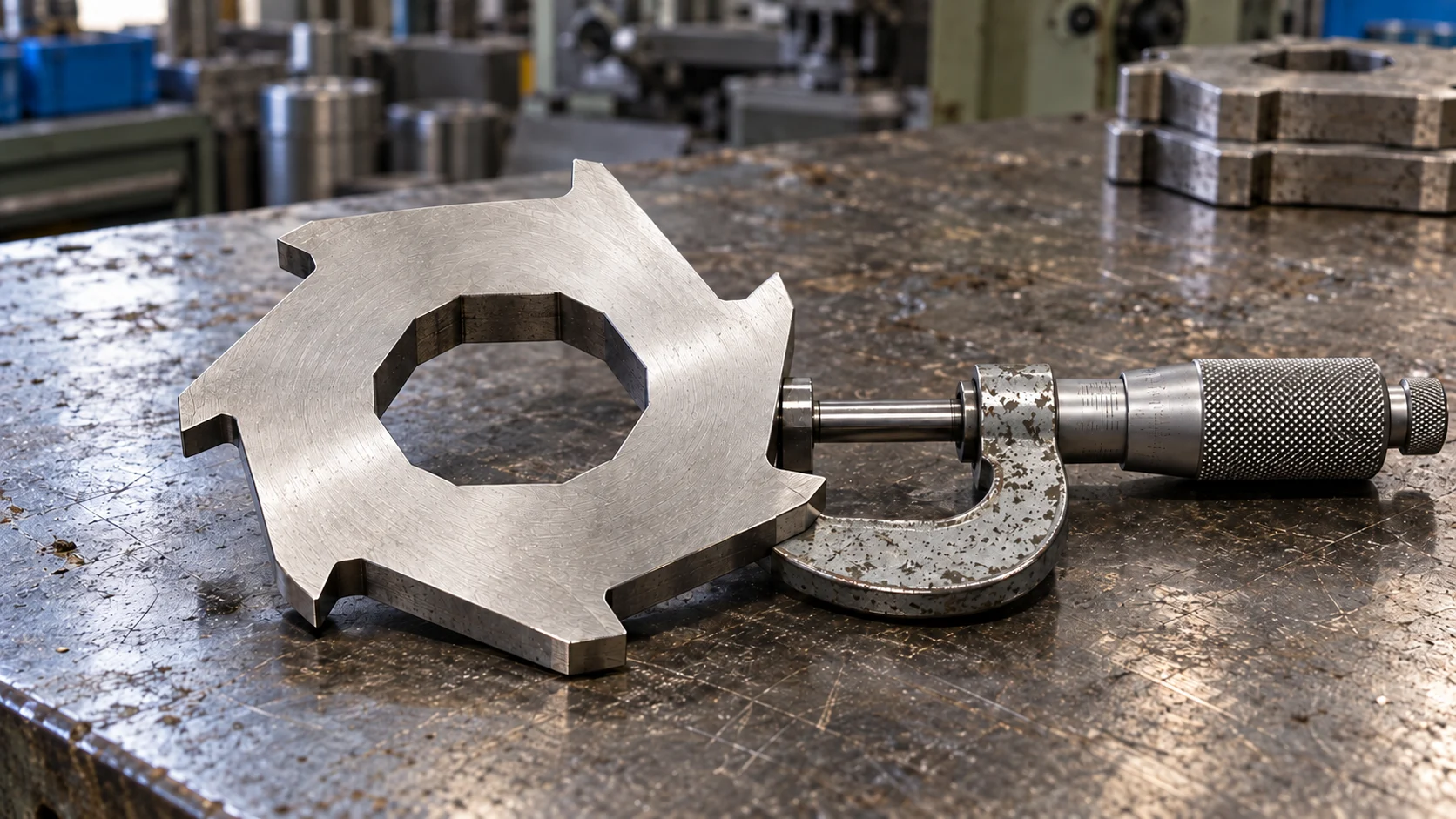
Prefer the approved drawing and a traceable reference part. When only used parts are available, retain their identity and condition, and ask which features remain suitable for determining nominal geometry. One value taken across a worn or damaged surface should not silently become the manufacturing requirement.
الـ shredder blade measurement guide helps organize the information to collect. Ask the supplier to identify unresolved dimensions and tolerances rather than treating every photograph as a confirmed measurement.
Inspection and access must follow the equipment instructions and the site’s hazardous-energy control procedure. The OSHA hazardous-energy overview explains why unexpected startup and stored energy matter during servicing. An emergency-stop button alone is not verified energy isolation.
Approve Geometry and Material as Separate Decisions
Material grade and heat treatment belong in the specification, but they do not correct an incompatible bore, tooth outline or assembly arrangement. Likewise, matching the geometry does not prove that the supplied material and condition meet the order.
For an equivalent replacement, retain the approved requirements and identify any exceptions before manufacture. For a proposed alternative, ask for the reason, affected requirements and verification plan. Avoid an order description that promises only better steel without defining the baseline or the agreed change.
| Purchase route | Establish first | Approval record |
|---|---|---|
| Equivalent replacement | Approved geometry, material requirements and part identity | Confirmation of conformity and declared exceptions |
| Reproduction from a used sample | Condition history and unresolved original dimensions | Agreed manufacturing drawing before production |
| Revised tooth profile or thickness | Material/output problem and affected assembly relationships | Approved revision and representative verification |
| Cutter-and-spacer combination | Types, positions, retained parts and supply boundaries | Controlled component list and assembly responsibility |
الـ صفحة شفرات آلة التقطيع ثنائية المحور من NJDETE is the relevant product entry for discussing replacement cutters. Custom manufacture from drawings or samples still requires specification agreement; it does not establish that any proposed design can be installed on an existing machine.
Use Operating Video as Context for the Application
The NJDETE channel clip below provides a short operating reference. It can help describe visible material presentation and cutting action. It does not reveal every cutter dimension, hidden spacer relationship, heat-treatment result or measured output distribution.
Watch the original NJDETE video on YouTube.
For an alternative design, request a record associated with the identified machine configuration, accepted feed and required result. Compare equivalent working conditions. Keep rejected material and interruptions visible so that an attractive short clip does not replace the acceptance record.
Prepare an Unambiguous Blade RFQ
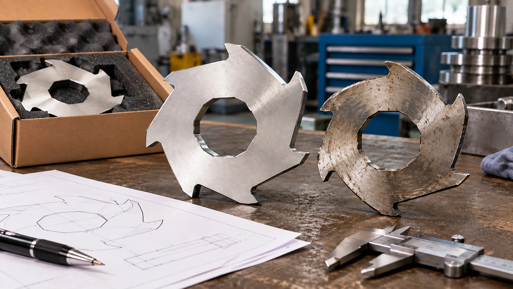
The buyer’s inquiry should make unresolved questions easy to find. Separate confirmed information from approximate measurements and unknown details. Where the design is changing, keep the original baseline and proposed revision together.
| RFQ item | Information to include |
|---|---|
| Equipment | Manufacturer, model, serial reference and cutting-system type |
| Parts | Drawing revision, cutter and spacer identities, quantities and positions |
| التطبيق | Feed examples, normal contamination and preparation method |
| النتيجة المطلوبة | Receiving specification, rejected fraction and available samples |
| Existing condition | Wear, damage, regrinding, retained parts and relevant history |
| Proposed change | Geometry or material changes and approval responsibility |
| Delivery | Identification, packing, inspection evidence and discrepancy process |
Keep supplied part types traceable to the approved order during packing and receipt. If marking, quantity or dimensions differ, resolve the discrepancy before installation. The دليل استبدال الشفرة covers the wider replacement decision; this article defines the design and specification information that supports it.
الأسئلة الشائعة
What Determines a Shredder Blade Design?
The feed, required output, machine arrangement and approved interfaces must be considered together. Tooth count, thickness, bore, material requirements and orientation each need a defined specification. No single feature establishes suitability for every application.
Does a Higher Tooth Count Improve Throughput?
Not automatically. Ask how the complete profile and arrangement relate to the actual feed and output requirement. Compare representative trial results under equivalent conditions rather than selecting only by the number of teeth.
Will Thinner Blades Produce Smaller Pieces?
A thickness change can alter the cutting arrangement, but it does not guarantee a particular complete output distribution. Define the rejected fraction and review the entire process and assembly before approving a revision.
Can Existing Spacers Be Reused With New Blades?
Reuse depends on the specified arrangement, component identity and condition criteria. Confirm retained parts with the responsible technical team. If cutter thickness or another interface changes, assess the affected assembly before ordering.
Are Two Cutters Interchangeable if Their Bores Match?
A matching bore alone is insufficient. Diameter, thickness, profile, orientation, position and associated components still require confirmation against the approved specification. Physical fit on the shaft is only one part of the review.
Can a Supplier Manufacture From a Worn Blade?
A used sample can support identification and measurement, but wear may obscure the original geometry. Agree which dimensions are reliable, resolve missing information and approve the manufacturing drawing before reproduction.
Should Poor Gripping Always Lead to a New Tooth Profile?
First review feed presentation, material form, cutter condition and the observed symptom. Record where and when the problem occurs. A design change should address the established cause and have a defined verification method.
What Should a Complete Blade Set Include?
Define the set through a parts list. State whether it includes cutters, specified spacers, associated components or an assembled unit, and identify retained parts. Quantities and revisions should be explicit before quotation approval.
Confirm the Design Before Manufacturing Replacement Cutters
Send NJDETE your blade-design and replacement inquiry with machine identity, drawings or traceable samples, cutter and spacer quantities, material information and the required output. Highlight any proposed change from the approved arrangement.
Ask for a clear specification, supply scope and list of unresolved questions before production. That gives purchasing, maintenance and the component manufacturer a common basis for reviewing the replacement and its acceptance evidence.