

Guía para la sustitución de cuchillas de trituradora: planificación segura, inspección y datos para la solicitud de presupuesto
Release time: 2026-09-23
Quick answer: Shredder blade replacement should begin with verified energy isolation, not with removing a cutter. A reliable replacement plan records the original cutter-and-spacer sequence, checks the shaft and bearings, measures every critical interface, rebuilds the stack to the machine manufacturer’s requirements, and validates the machine first without load and then with representative feedstock. Blade dimensions, material and tooth geometry must be matched to the actual shredder and working conditions; model name alone is not enough.
When Does a Shredder Need Blade Replacement?
A worn edge does not automatically mean that the entire cutter stack must be replaced. Depending on blade geometry, remaining material, damage depth and manufacturer limits, a cutter may be suitable for regrinding, individual replacement or full-set replacement. The decision should be based on inspection and measurement rather than operating hours alone.
Common warning signs include:
| Estado observado | What it may indicate | What to verify before ordering |
|---|---|---|
| Rounded or polished cutting edges | Progressive abrasive wear | Edge condition around the full circumference; change in output and motor load |
| Chipped teeth | Impact from hard contamination, insufficient toughness or incorrect clearance | Chip depth, crack propagation, feed contaminants and tooth engagement |
| Uneven wear across the shaft | Uneven feeding, stack misalignment, shaft movement or local contamination | Cutter thickness, spacer condition, shaft runout, bearings and feed distribution |
| Wider or less consistent discharge | Reduced bite, excessive clearance or mixed cutter condition | Cutter profile, counter-component condition and downstream size requirement |
| More frequent reversals or jams | Blunt cutters, unsuitable feed geometry or foreign objects | Feed dimensions, contamination, drive load and chamber condition |
| Abnormal heat, vibration or noise | Possible bearing, shaft, fastener or stack problem | Stop and inspect the complete mechanical system; do not assume blades are the only cause |
These symptoms are diagnostic starting points, not proof of a single failure mode. A replacement cutter will not correct a bent shaft, damaged bearing, loose stack, unsuitable feedstock or incorrect operating procedure. For localized tooth or edge fracture, see Por qué se astillan o se agrietan las cuchillas de la trituradora before ordering replacement cutters.
First Identify the Blade Family
Before measuring or requesting a quotation, confirm whether the machine uses interlocking cutter discs, straight rotor knives, bed knives, counter knives or another cutting arrangement.
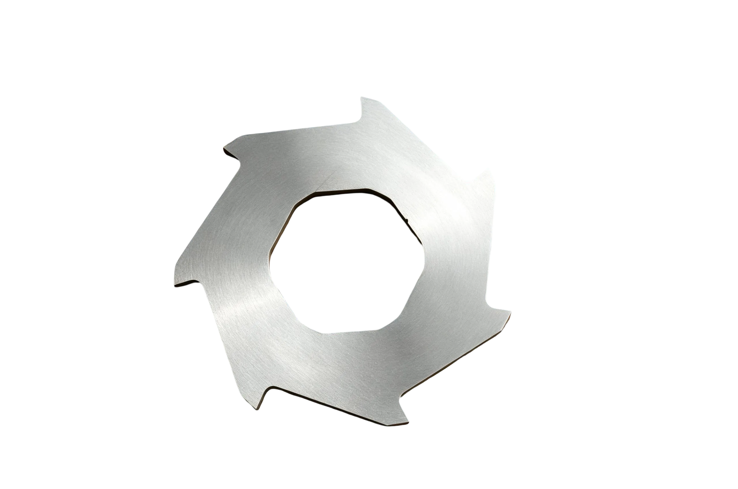
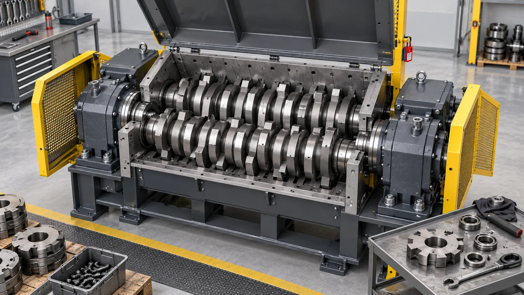
De NJDETE Página sobre las cuchillas de la trituradora de doble eje describes disc-type cutters for low-speed, heavy-load shearing. These are different from the straight adjustable knives used in many plastic crushers and granulators.
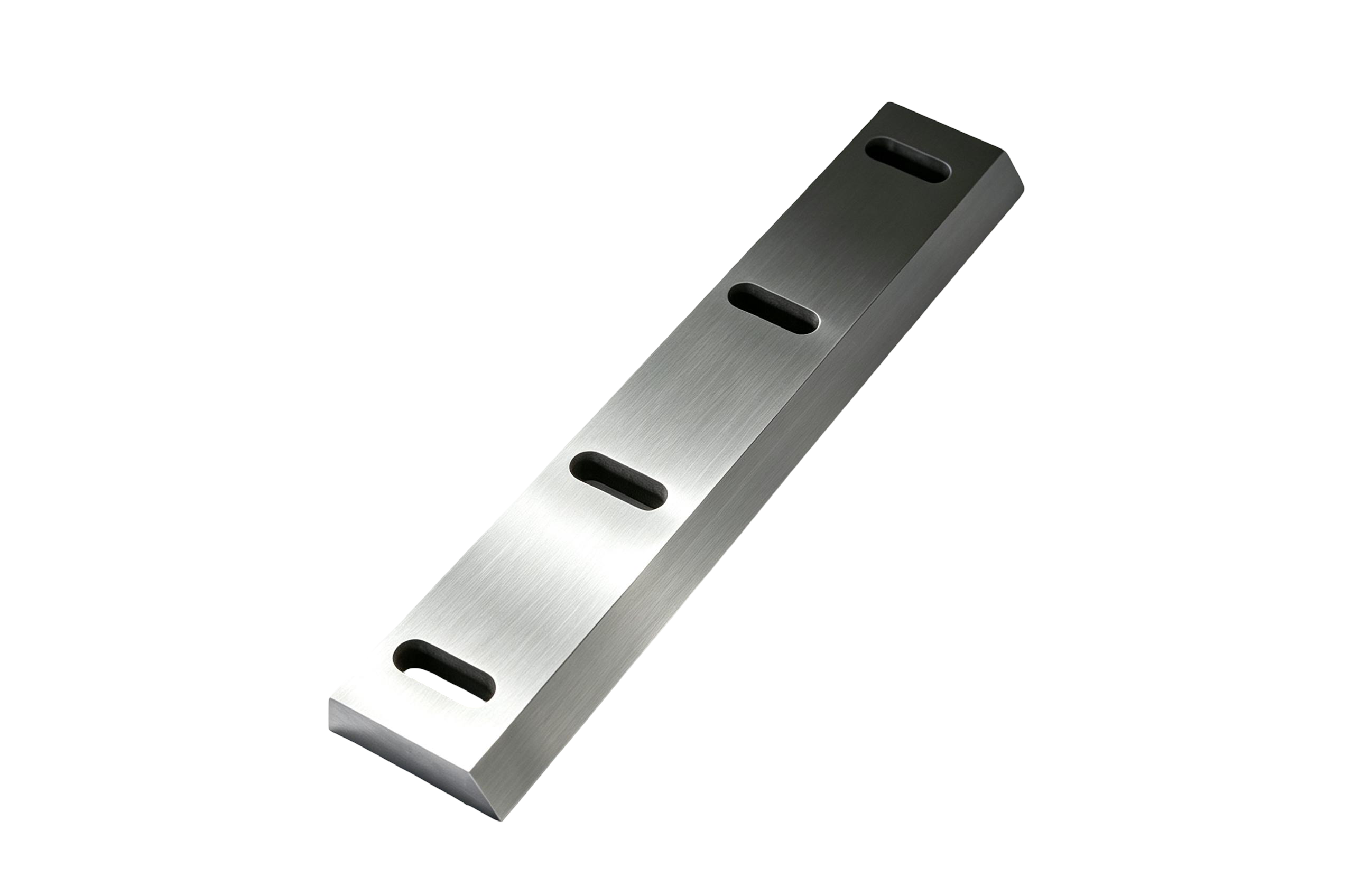
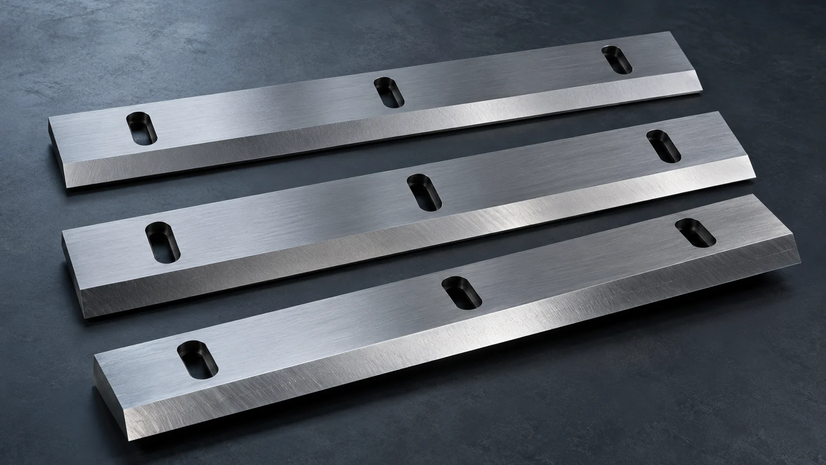
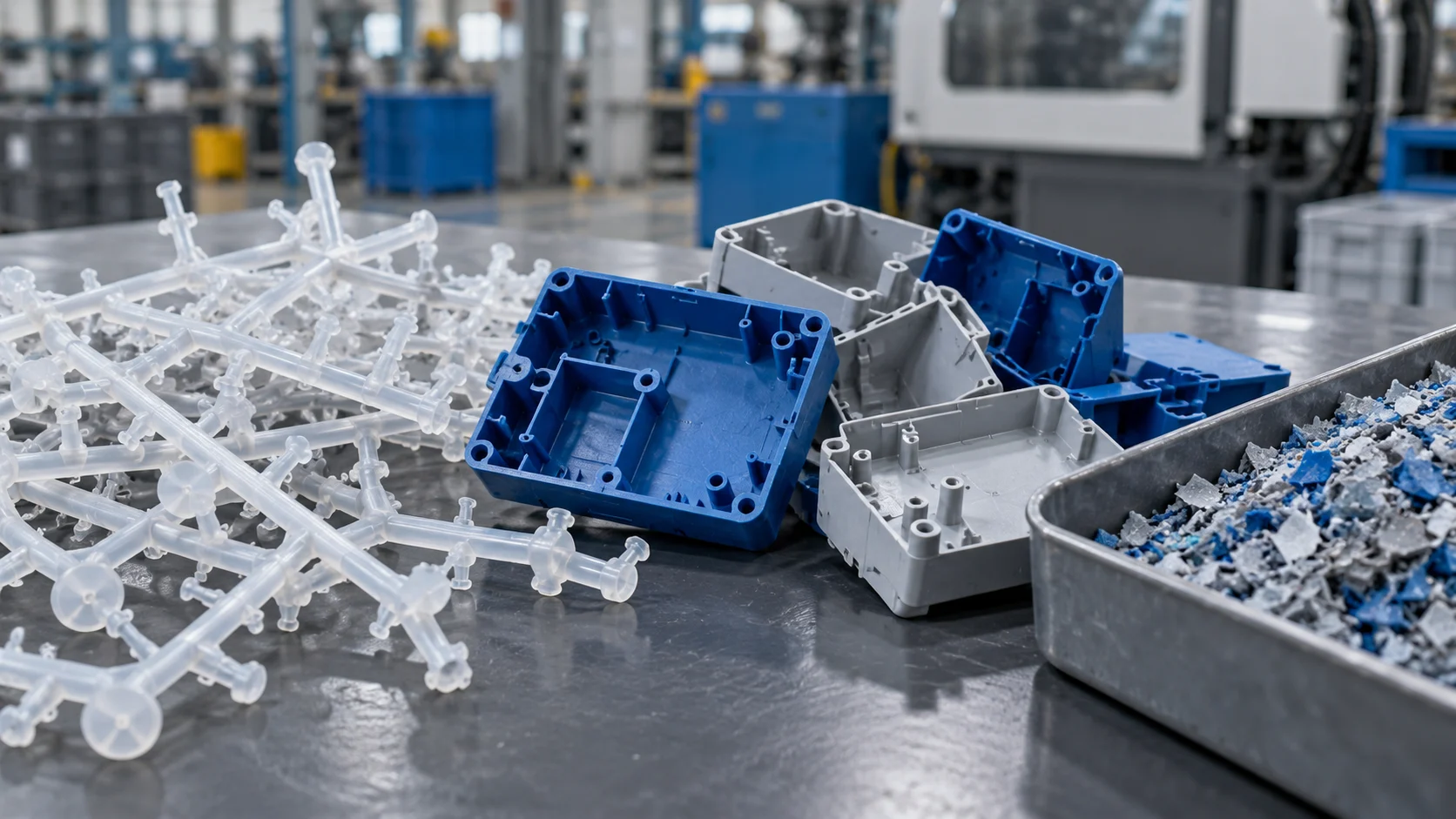
If the downstream process uses a granulator after primary shredding, review the separate plastic crusher blade configuration as part of the complete size-reduction line.
Safety Comes Before Disassembly
Blade replacement exposes personnel to sharp edges, heavy components, pinch points and stored energy. Only trained and authorized personnel should perform the work with the correct lifting, blocking and personal-protective equipment.
For workplaces subject to United States requirements, OSHA’s 29 CFR 1910.147 control-of-hazardous-energy standard addresses servicing and maintenance where unexpected energization, startup or release of stored energy could cause injury. Other countries and sites may impose different or additional requirements.
A machine-specific procedure should, at minimum, identify:
- every electrical, hydraulic, pneumatic, gravitational and mechanical energy source;
- the authorized isolation and lockout points;
- how zero-energy status will be verified;
- how heavy shafts, cutters and guards will be supported and lifted;
- who is authorized to remove locks and restore the machine to service;
- the controlled test procedure after reassembly.
ISO 12100 provides general principles for machinery risk assessment and risk reduction. It is a design and risk-assessment framework, not a substitute for the shredder manufacturer’s maintenance manual or local legal requirements.
Safety boundary: This article is a planning and purchasing guide. It is not a machine-specific disassembly instruction. Shaft removal direction, retaining systems, fastener torque, lifting points and alignment procedures vary by machine.
Information to Record Before Removing the Cutter Stack
Documentation made before disassembly is often more valuable than photographs taken after parts are mixed together. Record the original arrangement while the machine is still intact.
Photograph and mark
- left and right shaft orientation;
- drive side and non-drive side;
- cutter tooth direction and relative timing;
- cutter and spacer sequence from a fixed datum;
- retaining nuts, sleeves, keys, splines and shoulders;
- side combs, counter knives and cleaning fingers;
- bearing housings, seals and shims;
- any factory match marks.
Use durable tags and a numbered layout board so that parts cannot be reversed or exchanged unintentionally. Do not rely on memory or one wide-angle image.
Measure the interfaces
For each cutter family, record:
- outside diameter;
- cutter thickness;
- bore diameter and tolerance, if available;
- keyway, spline or polygonal-bore geometry;
- tooth count, tooth height and profile;
- edge bevel and cutting direction;
- spacer outside diameter, bore and thickness;
- shaft section and usable stack length;
- overall assembled stack width;
- quantity per shaft and total quantity.
A drawing, an undamaged sample and verified measurements provide a stronger basis for replacement than a machine photo alone.
A Practical Shredder Blade Replacement Workflow
The following workflow is intentionally generic. The machine manual and site safety procedure take precedence.
- Define the maintenance scope. Decide whether the task is inspection, regrinding, partial replacement or full-set replacement. Record the operating symptoms, processed material and recent contamination events. If the machine has abnormal vibration, bearing temperature or shaft movement, expand the inspection beyond the cutters.
- Empty and prepare the machine. Stop feed, clear loose material using the approved procedure, position the machine for maintenance and establish an exclusion zone. Do not reach into a chamber that has not been isolated and verified.
- Isolate and verify hazardous energy. Apply the site’s lockout/tagout procedure, release or restrain stored energy and verify that the isolation is effective. Control keys and access according to the authorized procedure.
- Preserve the original stack sequence. Photograph, mark and map every cutter and spacer. Record the tooth orientation and shaft relationship. Keep left- and right-shaft components separated.
- Remove components with suitable handling equipment. Follow the manufacturer’s method for guards, bearing housings, retainers and shafts. Cutter discs and shaft assemblies can be too heavy for manual handling. Use rated lifting equipment and protect cutting edges from impact.
- Inspect the entire mechanical stack. Clean and inspect cutters, spacers, shaft interfaces, threads, keys or splines, bearings, seals, side combs and retaining components. Look for fretting, cracks, distortion, corrosion, abnormal polish and dimensional loss.
- Confirm replacement-part conformity. Compare replacement cutters against the approved drawing or reference sample. Verify dimensions, tooth profile, cutting direction, material certificate if specified, heat-treatment record if contractually required, quantity and identification.
- Rebuild in the documented order. Reassemble the stack according to the machine manufacturer’s sequence, orientation, clearances, lubrication instructions and fastener specifications. Do not copy a torque value from a different shredder or generic online table without engineering confirmation.
- Check freedom of movement before power is restored. Where the machine design and manufacturer’s procedure permit, verify that shafts and cutters do not mechanically interfere. Confirm guards, covers, tools and loose parts are accounted for before controlled re-energization.
- Validate under controlled conditions. Follow the authorized return-to-service procedure. Begin with the prescribed no-load checks, then use a small quantity of representative feedstock while monitoring sound, vibration, temperature, current and discharge. Stop if the machine behaves abnormally.
Replace One Cutter or the Complete Set?
The right choice depends on damage distribution and stack geometry.
| Condición | Typical decision path |
|---|---|
| One cutter damaged by an isolated contaminant event | Individual replacement may be possible if dimensions and remaining-stack condition can be matched |
| Several cutters have similar progressive wear | Regrinding or replacing a matched group may maintain more consistent engagement |
| Uneven cutter thickness after repeated regrinding | Review the complete stack, spacer relationship and assembled width |
| Cracks, deep tooth loss or heat damage | Remove the affected cutter from service and inspect adjacent components |
| Unknown cutter history or mixed undocumented parts | Measure and document the full set before ordering |
| Shaft, bearing or retaining damage | Correct the mechanical cause before treating the problem as blade-only wear |
Mixing new and heavily worn cutters may change engagement, load distribution and output. The acceptability of a mixed stack must be assessed against the actual design; it should not be assumed.
Material and Heat Treatment: What Buyers Should Specify
Material grade alone does not predict blade performance. Wear resistance, toughness, hardness distribution, heat treatment, machining accuracy, feed contamination and operating practice interact.
NJDETE lists 9CrSi and H13 alloy tool steel options for its double-shaft shredder cutters, with material customization available. Selection should consider:
- abrasive versus impact-dominant feedstock;
- flexible material that wraps versus brittle material that fractures;
- metal contamination and tramp-object risk;
- tooth profile and cutter thickness;
- required toughness at the cutter root;
- regrinding plan and remaining usable geometry;
- mating shaft, spacer and side-component condition.
Do not request the highest possible hardness without discussing impact risk. A harder edge may improve wear resistance in one application but may be less tolerant of severe impact in another. The target should be an application-appropriate balance, documented between buyer and supplier.
RFQ Checklist for Replacement Shredder Blades
An accurate request for quotation should contain enough information to identify the mechanical interface and the working condition.
Machine information
- machine manufacturer and model;
- serial number or manufacturing year, when available;
- shaft type and number of shafts;
- motor and reducer information if relevant to the application review;
- photographs of the complete machine and open chamber.
Cutter information
- dimensioned drawing or readable sketch;
- outside diameter, thickness and bore;
- keyway, spline or shaped-bore details;
- tooth count and profile;
- quantity per shaft and total quantity;
- cutter-and-spacer sequence;
- existing material and hardness, if verified;
- undamaged sample availability.
Application information
- exact material being processed;
- minimum and maximum feed dimensions;
- expected contaminants;
- current output condition and target result;
- dry, wet, hot, corrosive or dusty working conditions;
- operating hours, duty cycle and observed failure mode;
- photographs of worn, chipped or cracked areas.
You can send drawings, measurements and application information through the NJDETE contact page. For available machine and blade families, review the Centro de productos NJDETE y shredder product category.
Quality Records Worth Requesting
Not every order requires the same documentation. Agree on the required records before production rather than after delivery.
Depending on the contract and risk level, buyers may request:
- approved drawing revision;
- material identification or certificate;
- heat-treatment record;
- dimensional inspection report;
- hardness inspection at agreed locations;
- quantity and part identification;
- packaging and corrosion-protection method;
- sample approval before batch production.
Only claim a certificate or inspection record on the published page if NJDETE can actually provide it for that order.
Preguntas frecuentes
Can worn shredder blades be resharpened?
Some cutters can be reground if sufficient usable material remains and the tooth geometry, stack width and engagement can be restored within the machine manufacturer’s limits. Cracked, severely chipped, distorted or heat-damaged cutters may not be suitable. Inspection should precede the decision.
Can one damaged cutter be replaced without replacing the full set?
Sometimes, but the new cutter must be compatible with the worn stack in thickness, diameter, tooth geometry and engagement. Mixing substantially different cutter conditions can change load distribution and output. Confirm the arrangement with the machine or cutter supplier.
What measurements are essential for a replacement cutter?
At minimum, provide outside diameter, thickness, bore geometry, tooth count and profile, spacer dimensions, quantity and stack sequence. A verified drawing or undamaged sample is preferable to measurements alone.
Does blade thickness determine final output size?
Blade thickness influences the cutter stack and bite pattern, but it does not independently guarantee a final particle size. Tooth geometry, clearances, shaft speed, material behavior, screen or downstream equipment and operating conditions also matter.
How often should shredder blades be replaced?
There is no universal interval. Replacement depends on feedstock, contaminants, cutter material, heat treatment, duty cycle, loading and acceptable output. Use inspection trends and operating data rather than an unsupported hour-based promise.
Are shredder blades and plastic crusher blades interchangeable?
No. Double-shaft shredders commonly use interlocking cutter discs, while many plastic crushers use straight rotor and bed knives. Their geometry, mounting, speed and cutting action differ. Specify the actual machine and blade family.
Technical References and Content Boundary
- OSHA 29 CFR 1910.147 — The Control of Hazardous Energy
- ISO 12100:2010 — Safety of Machinery: Risk Assessment and Risk Reduction
- NJDETE Double-Shaft Shredder Blades
- NJDETE Plastic Crusher Blades
This article provides general selection and maintenance-planning information. It does not replace the machine manufacturer’s manual, a site-specific risk assessment, applicable law or instructions from qualified maintenance personnel.